Enginursday: Innovative Testbed Design (Part 1 of 2)
It’s fun to be on the quality control side of things. Not only do we get to play with all the new widgets ahead of release, we are constantly faced with new challenges and pushed to innovate testbed design. Sometimes new products require new features on a testbed, and that pushes us to innovate. Sometimes we discover a reliability issue in production, and that pushes us to revise hardware to make something more robust. We’ve progressed a lot over the years. Let’s look back and highlight some of the innovations that allow us to design, build and code new testbeds really quickly.
Back in the day
We used to have some fairly finicky test fixtures back in the day. As a production tech in 2007, I remember very careful handling the fixtures to make sure I didn’t break any of the many, many green wires (and I was lucky if it worked 50 percent of the time).
Test fixture from 2008 using bare male headers to connect to the product…eeek!
As you can see above, this early testbed uses male headers facing up to make a temporary connection to the product. The technician would have to slide the headers into the products PTH headers on the side of the product, and then apply pressure to either side to attempt to make a connection during testing. It took a very steady hand to get this sucker to work every time. If you’d like to check out more info about our older test fixtures and general quality control progress, check out these tutorials:
- Sneaky Footprints (2008)
- PogoBeds: SparkFun Production and Testing (2009)
- Ganged Programming with AVR ISP MKIIs (2011)
- Constant Innovation in Quality Control (2013)
- Enginursday: A new and improved IOIO-OTG! (2016)
- Raspberry Pi Stand-Alone Programmer (2018)
Custom layouts
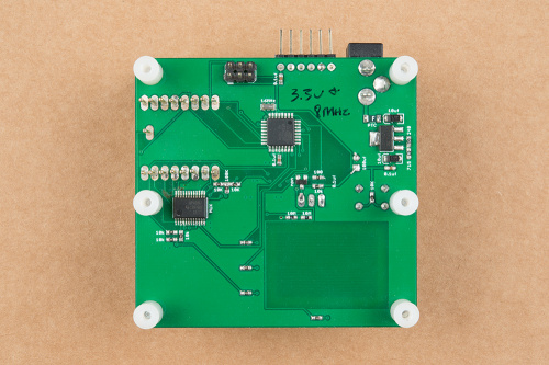
Testbed made with custom PCB layout using mostly SMD commponents
In 2009 (ish), we started laying out custom PCBs for every new testbed. This was nice because it kept the designs small and self contained. Another advancement here was using pogopins to make a nice temporary connection to the product. This style of testbed design actually proved to be the “norm” for quite a while. At the time, and still to this day, we build all of our test fixtures by hand with an iron (even all the SMD parts). We just couldn’t justify ordering a stencil when we could get by with an iron and a steady hand. Even if it did have some more difficult parts that require hot air to place, we wanted to keep our rework chops up to snuff!
Modular Designs
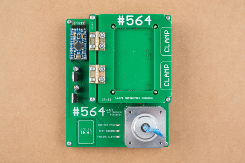
Testbed designed around an Arduino Pro Mini and a custom base layer PCB
Here we have a stepper motor driver testbed. This is a good example of how we were able to use an Arduino Pro Mini as the main “brain” of the testbed, and then add the additional components needed to a custom PCB layout. This approach to testbed design became known as the “modular” approach, and cut down on the SMD work needed to assemble a testbed. It was also nice to know that production had tested the Pro Mini on your testbed, cutting down on any troubleshooting when you first power up.
Testbed using a Arduino Mega Pro and a custom base layer PCB
Here is a second example of a “modular” designed testbed, except this time we needed more GPIOs. This required using a Arduino Mega Pro instead of the Pro Mini. This again helps cut down on assembly time, although soldering up all of the PTH headers on the Mega Pro Board, and its mating female headers on the testbed, still does take some time. You may notice that this has quite a mix of color in the PCBs. I seem to remember having to rush order this from OSH Park in order to keep up with the Free SoC2 product launch schedule. Thanks OSH Park!!
Stand-alone programming
It had always been a dream of ours to move testing and programming away from using the production techs' Windows computers. This is because each time Windows would auto-update, we would be bombarded with driver issues. We ended up going with a Raspberry Pi-based solution and designing our own custom HAT, the SparkFun Pi AVR Programmer HAT. Read all about it in the following tutorial:
Custom Generic Hardware
As we designed more and more testbeds, we found that they needed similar things. This is why it made sense to make a single design that included most of the features we needed, and then make custom “daughter” boards that are specific to each product.
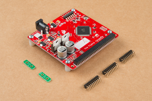
The Flying Jalapeno testing tool in all its glory!
Above, is our in-house designed Flying Jalapeno. We use this on most new test fixtures, and it dramatically decreases testbed design and assembly time. Stay tuned for a more in-depth look at the hardware design of this tool, and the accompanying Arduino code library.
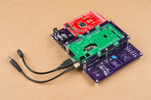
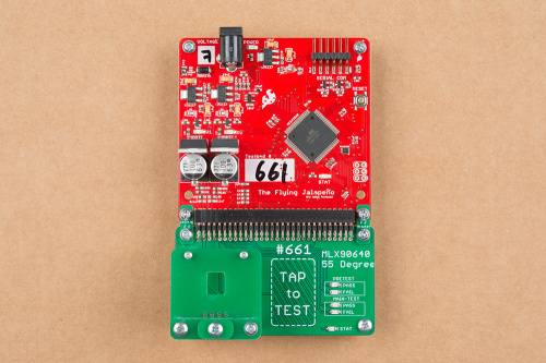
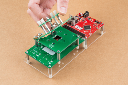
Testbed for an IR Array sensor using the Flying Jalapeno
As you can see above, this testbed is made up of two parts. The top section (the red PCB) is the Flying Jalapeno, and the bottom section (the green PCB) is the custom daughter board for the product. This particular testbed is designed to test the SparkFun IR Array Breakout. Because we receive the Flying Jalapeno assembled (and tested) from production, the assembly time for this test fixture is reduced to simply building up the smaller bottom section. That’s just a 2x30 header, five LEDs and four pogopins. Piece of cake!
Laser-cut Acrylic parts
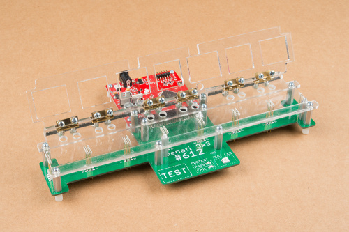
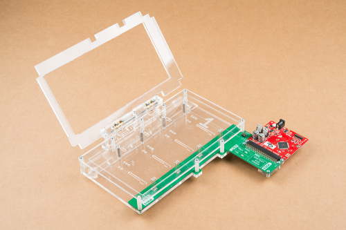
Testbed using the Flying Jalapeno and lazer-cut acrylic parts
Here is a fairly recent testbed design for testing the Lumenati 3x3. Occasionally, we will cut certain layers on our laser cutter using clear acrylic. Not only does this look slick, but it saves us money, because previously we would have been ordering those layers from a PCB fab house and that can get pretty costly for large testbeds. Also, this allows us to fine tune the laser-cut layers in house. We can tweak the design as necessary and have a new part cut in just minutes!
A few more beauties
GatorBit testbed
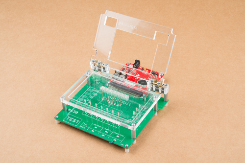
OpenLog testbed with unique “waffle top”
RedBoard Edge testbed
Stay tuned for Part 2
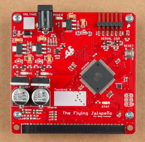
Join us next week as we give a more in-depth look at all of the hardware choices inside the Flying Jalapeno, and dive into the accompanying Arduino code library. For a sneak peak, take a close look at the following picture, and see if you can spot any design flaws. There are actually a few things that we plan to change on a future revision to this design, but I challenge you to find as many as you can. The first commenter to spot the flaw I am thinking of will get extreme street cred and I will personally mail you a Flying Jalapeno!
Detailed pic of the Flying Jalapeno
Also, if you have any testbed design stories to share (I’m looking at you, #773), or any questions about SparkFun testbeds, please feel free to post a comment below. Thanks for reading and we’ll see ya next week!
Via Westline T2B http://www.rssmix.com/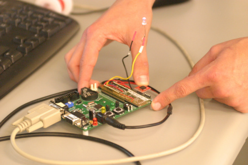
Comments
Post a Comment